
Yongda
Choosing the right Full Port Ball Valve begins with understanding the system, not the product photograph. A full-bore passage allows media to move with minimal restriction, which can reduce pressure loss and simplify pipeline cleaning. However, bore size alone does not guarantee reliable service. The valve must match the fluid, operating pressure, temperature, connection type, and cycling frequency. A valve handling clean water may fail quickly with abrasive slurry. That difference matters.
In practical installations, I examine the pipeline, confirm the flow direction, and check available space around the handle or actuator. Stainless steel may suit corrosive environments, while carbon steel can provide practical strength in less aggressive systems. Seat materials also deserve close attention. PTFE, reinforced PTFE, and metal seats behave differently under heat, pressure, and repeated operation. The wrong seat can leak, even when the body appears robust.
Ask specific questions.
What will pass through it?
Will maintenance require frequent removal? A lockable handle may improve operational safety, while an automated actuator can support regular process control. End connections should align with existing piping standards and installation practices. Certifications and test records from a qualified manufacturer add confidence, but paperwork should never replace technical verification.
There is no universal best valve. A cheaper option may become expensive after premature replacement, yet an oversized valve can waste budget and space. Review real operating conditions, consult experienced engineers, and compare documented performance. A careful choice should work quietly, seal consistently, and remain serviceable long after installation. That is the standard worth pursuing.
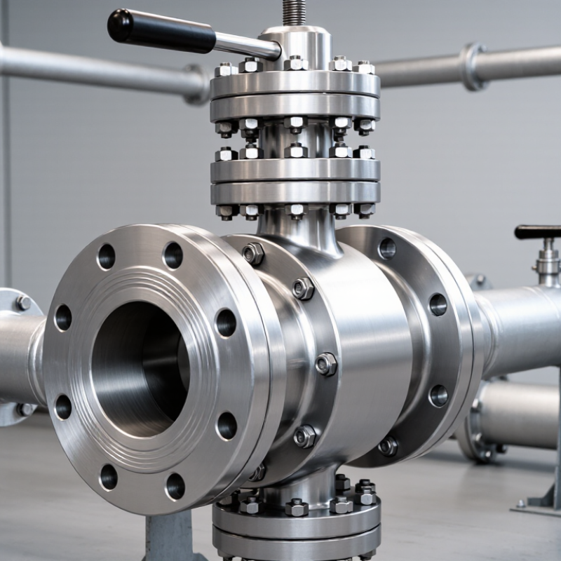
A full port ball valve has a ball opening that closely matches the connected pipe’s inside diameter. When the handle turns 90 degrees, the bore aligns with the pipeline. Fluid then passes through with minimal obstruction. In the closed position, the ball rotates its solid surface across the flow path, while seats create the seal.
This design can reduce turbulence, velocity changes, and pressure loss. However, “minimal” does not mean zero. The valve still contains seats, seals, and connection transitions. The Hydraulic Institute’s ANSI/HI 9.6.7 guidance stresses that system pressure loss depends on the complete flow path, not one component alone. A full port valve is useful for viscous liquids, slurry service, piggable pipelines, and applications requiring easier cleaning.
Selection should begin with media, pressure, temperature, and pipe size. Check the pressure-temperature rating under ASME B16.34. Confirm shell and seat testing requirements through API 598 or ISO 5208. For compressed-air systems, U.S. Department of Energy guidance reports that leaks can waste 20% to 30% of compressor output. Poor valve selection may worsen that loss. Yet valve leakage is only one possible cause. That assumption is too neat. Material compatibility, installation quality, cycling frequency, and actuator sizing also matter. A stainless body may resist corrosion, but its seats could still fail under heat, chemicals, or abrasive particles. Choose the bore for actual flow needs, not appearance alone.
What a Full-Port Ball Valve Is and How It Works
A full-port ball valve has a ball opening that closely matches the inside diameter of the connected pipe. This creates a nearly straight flow path, helping reduce velocity increase and pressure loss compared with a smaller reduced-port opening.
The chart compares calculated flow-passage areas for common NPS Schedule 40 pipe inside diameters with a hypothetical reduced port measuring 70% of the pipe bore. The full-port areas are based on the circular pipe-bore formula, while actual valve performance also depends on valve geometry, fluid properties, pressure, temperature, and flow coefficient.
When choosing a valve, match the port and connection size to the piping system, then verify pressure rating, temperature range, materials, actuation requirements, and the manufacturer’s flow data.
A full port ball valve keeps the opening close to the connected pipe’s internal diameter. This reduces turbulence and limits pressure loss across the valve. It suits pipelines carrying water, hydrocarbons, steam, and abrasive mixtures. The choice becomes more important when pumps operate near their pressure limits. Every unnecessary restriction can increase energy demand.
The U.S. Department of Energy’s Improving Compressed Air System Performance sourcebook reports that leaks can waste 20–30% of compressor output. A restricted valve can add another avoidable burden. Crane Technical Paper No. 410 provides established methods for estimating pressure loss, velocity, and flow behavior. Engineers should calculate these values instead of selecting by pipe size alone. A full port design is especially practical for pigging systems, high-flow transfer lines, and services containing suspended solids.
Reduced port valves may cost less and fit compact installations. They can also control flow adequately when pressure loss remains acceptable. In field reviews, I have seen full port valves specified where space or throttling requirements favored another design. That choice deserved more checking. Confirm the media, temperature, pressure class, actuator torque, seat material, and cleaning method. ISO 5208 testing requirements can help verify shutoff performance. A larger bore does not fix poor installation, misalignment, or unsuitable sealing materials. The final decision should compare lifecycle energy use, maintenance access, and actual flow demand.
Choosing a full port ball valve starts with the fluid, not the pipe size. A full-bore passage reduces turbulence and helps protect flow-sensitive systems. In field inspections, engineers should record temperature, pressure, concentration, and contamination risks. Water, glycol, solvents, acids, and abrasive slurries can demand very different materials. Stainless steel may handle many fluids, but it is not automatically suitable. A seal that survives room temperature may soften near a heated process. That overlooked detail causes leakage and premature maintenance.
Tips: Compare the valve body, ball, stem, and seats separately. Check a compatibility chart, then confirm it with the fluid supplier’s safety data. For corrosive media, consider chemical concentration and operating temperature together. For slurry, inspect erosion resistance and avoid narrow passages that trap solids. If the fluid can freeze, plan drainage and thermal protection. Never size by pressure alone. Pressure alone misleads. I once saw a correctly rated valve fail because its seat material was mismatched. The pressure calculation was sound; the material choice was not.
Reliable selection also requires checking cycling frequency and cleaning methods. Steam sterilization, caustic washing, or repeated thermal shocks can age seals quickly. Choose a full port design when pigging, flushing, or low pressure loss matters. Still, larger openings do not fix poor material compatibility. Ask for documented test data, temperature limits, and pressure ratings. Leave room for uncertainty. Real fluids are often dirtier, hotter, or more concentrated than the design sheet suggests.
Choosing a full port ball valve starts with the pipeline, not the valve catalog. Measure the actual pipe inside diameter and compare it with the valve’s bore. A full port design should allow similar flow area, reducing turbulence and pressure loss. Do not select by nominal pipe size alone. Wall thickness and lining can change the internal opening.
Pressure selection requires more than matching the normal working pressure. Check the valve’s pressure rating at the highest operating temperature, including startup surges and pump shutdown. The media also matters. Water, steam, gas, and corrosive fluids may require different body and seal materials. I have seen valves selected correctly on paper but fail early because temperature was ignored. That shortcut is tempting, but imperfect.
Connection style must suit the installation and maintenance plan. Threaded ends work well on smaller lines, while flanged ends support heavier equipment and easier removal. Welded connections can provide a compact, durable joint, but they demand careful alignment and qualified procedures. Confirm flange dimensions, thread standards, face type, and gasket compatibility before ordering. Leave enough clearance for the handle and future servicing. A valve may fit the pipe yet remain impossible to operate. Check the manufacturer’s data sheet, inspection records, and applicable engineering standards. When conditions are uncertain, record the uncertainty instead of guessing.
How to Choose a Full Port Ball Valve?
A full port ball valve should operate smoothly, not merely fit the pipeline. During inspection, cycle the handle through 90 degrees and watch for sticking, uneven torque, or delayed movement. A clean-looking handle can hide a damaged stem seal. Check the actuator’s torque margin under actual pressure, not only on a workbench. Keep a simple record of cycle time, leakage, and abnormal noise. Small details matter.
Standards provide a useful baseline. ASME B16.34 covers pressure-temperature ratings and design requirements, while API 598 and ISO 5208 define pressure and leakage testing methods. Ask for test records, material certificates, and the correct pressure class. Standards do not replace site verification. Temperature, fluid cleanliness, installation position, and flow direction can change performance. I would also confirm that the bore matches the pipe size and that the valve does not create an unwanted restriction.
Maintenance needs should influence the purchase. Inspect the stem, gland area, body bolts, and nearby flanges during scheduled rounds. Avoid excessive packing adjustment; it may increase operating torque and accelerate wear. The U.S. Department of Energy’s Operations & Maintenance Best Practices Guide reports potential energy savings of 5–20% through stronger maintenance practices, depending on facility conditions. That figure is not a guarantee. It is a useful warning that reactive maintenance costs more than many teams expect. Field records should guide the service interval, because fixed calendar schedules can be wrong.
| Selection Dimension | What to Check | Typical Requirement or Data | Why It Matters | Inspection or Maintenance Action |
|---|---|---|---|---|
| Port Size | Compare the valve bore with the connected pipe internal diameter. | A full-port valve normally provides a bore close to the nominal pipe inside diameter, although the exact opening depends on the valve design and size. | Reduces flow restriction, pressure loss, turbulence, and the risk of interference with pigging or line-cleaning tools. | Verify the certified bore dimension and confirm that the pipeline cleaning tool can pass through the valve. |
| Valve Size | Match the nominal valve size to the pipe size and flange or fitting dimensions. | Common nominal sizes range from small instrument valves to large pipeline valves; the selected size must match the piping specification. | Incorrect sizing can cause installation problems, excessive velocity, or unnecessary cost. | Check the nameplate, dimensional drawing, face-to-face length, and connection dimensions before installation. |
| Pressure Rating | Confirm the required design pressure and design temperature, not only the normal operating pressure. | Typical flanged pressure classes include ASME Class 150, 300, 600, and higher; allowable pressure decreases as temperature increases. | The pressure-temperature rating determines safe operating limits. | Compare the valve pressure-temperature chart with the system design conditions and record test pressure separately from operating pressure. |
| Flow Direction | Determine whether the valve is intended for bidirectional or unidirectional shutoff. | Many floating and trunnion-mounted ball valves are designed for bidirectional shutoff, but the manufacturer’s flow-direction marking takes priority. | Incorrect installation may affect sealing, pressure relief, or cavity performance. | Follow the body arrow, cavity-relief direction, and installation instructions shown on the approved drawing. |
| Valve Body Design | Choose floating or trunnion-mounted construction according to size, pressure, torque, and service conditions. | Floating designs are common in smaller sizes; trunnion-mounted designs are often used for larger sizes or higher operating torque requirements. | The support arrangement affects operating torque, seat loading, and actuator sizing. | Check the design type, calculated breakaway torque, and allowable actuator output. |
| Body and Ball Material | Select materials compatible with the fluid, temperature, pressure, corrosion level, and erosion risk. | Common body materials include carbon steel, stainless steel, and alloy steel; the ball and stem may use compatible metallic materials or protective coatings. | Material incompatibility can cause corrosion, contamination, galling, or premature failure. | Review the material certificate, corrosion allowance, fluid compatibility, and any required surface treatment. |
| Seat Material | Consider fluid composition, temperature, pressure differential, abrasion, and chemical exposure. | Soft seats may use materials such as PTFE, reinforced PTFE, or other engineered polymers; metal seats are used for higher-temperature, abrasive, or severe services. | Seat selection directly affects leakage performance, service life, and operating torque. | Inspect seats for deformation, chemical attack, scoring, and leakage during scheduled shutdowns. |
| Temperature Range | Use the minimum, normal, maximum, and upset temperatures of the process. | The applicable temperature range is limited by the body, seat, stem seals, bolting, and any lining or coating. | Temperature can change pressure capacity, seat elasticity, seal performance, and actuator requirements. | Check the temperature rating on the datasheet and replace seals that show hardening, cracking, or extrusion. |
| End Connections | Select flanged, threaded, socket-weld, butt-weld, or other connections based on the piping design. | Flange dimensions may follow ASME B16.5 or ASME B16.47; butt-weld ends may follow ASME B16.25; threaded ends may follow the applicable piping specification. | Connection compatibility affects alignment, sealing, welding, and pressure integrity. | Check end dimensions, gasket type, bolt grade, weld procedure, and pipe alignment. |
| Manual Operation | Confirm that the handle or gearbox moves smoothly from fully closed to fully open. | A quarter-turn ball valve normally rotates approximately 90 degrees between the closed and open positions. | Hard spots, incomplete travel, or excessive torque may indicate contamination, seat damage, stem problems, or pressure locking. | Operate the valve periodically when permitted, verify the position indicator, and never use unauthorized extensions on the handle. |
| Actuator Selection | Size the actuator using the highest required torque, including breakaway, running, and end-position torque. | Pneumatic, electric, or hydraulic actuators may be used; the actuator must provide adequate torque under minimum supply conditions. | Undersized actuators may fail to operate the valve; oversized actuators can damage the stem or seats. | Test fail-open, fail-closed, or fail-in-place action as required by the process safety assessment. |
| Stem and Anti-Blowout Design | Verify that the stem is retained internally and that the packing or sealing system is suitable for the service. | A qualified anti-blowout stem design helps prevent stem ejection if internal pressure acts on the stem. | Stem retention and sealing are critical to personnel safety and fugitive-emission control. | Check for stem leakage, packing compression, corrosion, and abnormal movement. |
| Applicable Standards | Identify the governing product, design, testing, and installation standards in the project specification. | Common references include ASME B16.34 for valves, API 6D for pipeline valves, ISO 5208 for pressure testing, and ISO 5211 for actuator mounting interfaces. | Standards define dimensional, material, pressure, testing, and functional requirements. | Request the standard edition, compliance statement, inspection plan, and test records. |
| Pressure Testing | Verify shell, seat, and functional tests using the specified test medium and procedure. | ISO 5208 provides leakage-rate classifications and pressure-testing procedures; project specifications may impose additional requirements. | Testing confirms pressure boundary integrity and shutoff performance before commissioning. | Review calibrated test equipment, test duration, pressure values, leakage results, and signed test certificates. |
| Leakage Performance | Define the acceptable seat and stem leakage class before purchase. | Soft-seated valves commonly provide very low visible leakage when correctly selected and tested; allowable leakage depends on the specified standard and class. | Leakage can create safety, environmental, product-quality, or energy risks. | Monitor external leakage and verify shutoff performance during planned maintenance. |
| Installation Orientation | Check support, access, actuator clearance, drain or vent orientation, and pipeline cleanliness. | Ball valves should be installed without forced pipe alignment or external loads that exceed the design limits. | Poor installation can distort the body, increase torque, and damage seats or stem seals. | Flush the pipe, protect the bore during welding, align the ends, and confirm full accessibility for operation. |
| Cavity Pressure Relief | Determine whether trapped fluid in the valve cavity can be heated, vaporized, or over-pressurized. | Cavity-relief arrangements may be required for certain pipeline and process applications; the design must match the specified safety philosophy. | Thermal expansion of trapped liquid can create dangerous internal pressure. | Confirm relief direction, vent or drain provisions, and operating procedures before commissioning. |
| Maintenance Frequency | Base the schedule on service severity, operating cycles, fluid cleanliness, and safety criticality. | There is no universal interval; visual checks may be monthly or quarterly, while functional testing is often scheduled at planned shutdowns or according to risk. | A risk-based schedule avoids both neglected maintenance and unnecessary disassembly. | Record operating cycles, leakage, torque changes, repairs, and test results in the maintenance history. |
| Spare Parts and Repairability | Confirm availability of seats, seals, stem packing, gaskets, bolting, and repair instructions. | Repair kits should match the exact valve size, pressure class, material, seat design, and temperature range. | Correct spare parts reduce downtime and prevent incompatible replacement materials. | Maintain an identification record using the valve tag, serial number, drawing, material list, and revision level. |
| Safety and Lockout | Provide isolation, depressurization, venting, draining, and lockout procedures before servicing. | A closed valve must not be assumed to be a complete isolation barrier unless the system design and verification procedure permit that assumption. | Residual pressure or hazardous fluid can remain inside the valve cavity. | Follow the site permit-to-work and lockout/tagout procedure, verify zero energy, and use appropriate personal protective equipment. |
It has a ball opening close to the pipe’s inside diameter. Turning the handle 90 degrees opens or closes the flow path.
Its wide bore creates fewer flow restrictions. This can reduce turbulence and sudden velocity changes.A full bore does not mean zero loss.
It suits viscous liquids, slurry, steam, and high-flow transfer lines. It also works well in pipelines that require cleaning tools.
No. A reduced port valve may cost less and fit tight spaces. It may also work when pressure loss remains acceptable.That assumption needs checking.
Check the media, pressure, temperature, pipe size, seat material, and actuator torque. Consider cleaning access and expected cycling frequency.Do not choose by appearance alone.
It can control flow, but it is mainly suited to open-or-closed service. Frequent throttling may require a different valve design.The larger bore is not automatically better.
Leaks may waste 20% to 30% of compressor output. Valve leakage is only one possible cause.Poor fittings, damaged seals, and installation errors can also matter.
Review the required shell and seat testing procedures. Confirm the pressure-temperature rating for the actual operating conditions.A stainless body may still have unsuitable seats. Heat, chemicals, and abrasive particles can damage them.
Choosing the right Full Port Ball Valve begins with understanding its design and operating principle. A full port valve has an opening that closely matches the connected pipe diameter, allowing fluid to pass with minimal restriction and reducing pressure loss. This makes it a practical choice for applications requiring efficient flow, frequent cleaning, or the passage of soft solids. However, a reduced-port valve may be more suitable when compact size or lower cost is the priority.
Selection should also consider fluid temperature, pressure, chemical properties, and compatibility with valve materials such as the body, ball, and seals. Confirm that the valve size, pressure rating, and connection type match the piping system and installation conditions. Before purchase, review the operating method, cycle frequency, applicable industry standards, and maintenance requirements. A properly selected valve should provide reliable shutoff, smooth operation, easy inspection, and a service life suited to the demands of the system.