
Yongda Yongda

How to Choose the Right Hydraulic Ball Valve?

Time:2026-10-26 Author:Aria
0%

Choosing the right Hydraulic Ball Valve can determine whether a fluid system runs smoothly or fails under pressure. A suitable valve must match the medium, pressure, temperature, connection type, and required flow rate. It should also fit the operating environment, including moisture, vibration, dust, and limited installation space.

Small details matter. A valve installed near a hot pump may need different sealing materials than one used with clean water. Stainless steel bodies can support demanding environments, while carbon steel may offer practical strength for controlled industrial systems. The correct bore size also affects pressure loss and system performance. Too small, and the pump works harder. Too large, and control may become inefficient.

Safety comes first.

This guide explains how experienced engineers assess valve construction, port design, seal compatibility, actuation, and maintenance access. It also considers recognized manufacturing practices and supplier documentation, such as pressure ratings, material certificates, testing records, and installation instructions. These details help buyers compare products from reliable manufacturers instead of trusting appearance alone.

Still, selection is not always perfect. A specification sheet may overlook sudden temperature changes or real workplace conditions. I have seen technically suitable valves perform poorly because installers ignored pipe alignment or used the wrong sealant. That is why practical inspection matters. Before purchasing, confirm every operating requirement with the manufacturer or a qualified fluid-control professional. A careful decision can reduce leakage, downtime, replacement costs, and avoidable safety risks.
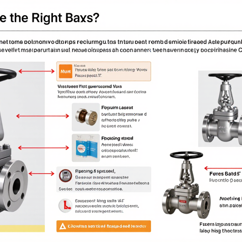
How to Choose the Right Hydraulic Ball Valve?

Define the Hydraulic Circuit’s Flow Rate, Pressure, Temperature, and Fluid

How to Choose the Right Hydraulic Ball Valve?

Choosing a hydraulic ball valve starts with the circuit, not the valve catalog. Record the normal flow rate and the highest expected flow rate. Peak demand matters more than an average reading. An undersized port creates pressure loss, heat, and sluggish actuator movement. Measure pressure near the valve, not only at the pump. Include startup surges and pressure spikes. Static pressure can mislead.

Temperature also affects valve performance. Check the fluid temperature during cold starts and continuous operation. A valve exposed to excessive heat may suffer seal hardening or leakage. Low temperatures can increase fluid viscosity and slow movement. I have learned that the operating range deserves more attention than the nominal temperature. Real machinery is rarely steady.

Fluid compatibility is equally important. Identify the exact hydraulic fluid, including mineral oil, water-based fluid, or biodegradable formulation. Confirm that the body, ball, seats, and seals tolerate that fluid. Viscosity affects flow behavior and required actuation force. Contamination matters too. Dirt can damage sealing surfaces. Use clean installation practices and flush the circuit when necessary. A pressure rating alone does not prove suitability. Check pressure, temperature, flow, and fluid together before selecting the valve.

Select Valve Size Using Flow Coefficient (Cv) and Pressure-Drop Data

How to Choose the Right Hydraulic Ball Valve?

Select Valve Size Using Flow Coefficient (Cv) and Pressure-Drop Data

Choosing a hydraulic ball valve starts with the required flow, not the pipe diameter alone. A correctly sized valve should pass the target flow while creating an acceptable pressure drop. Oversizing may reduce control accuracy and increase purchase cost. Undersizing can produce excessive velocity, noise, and unwanted heat.

For liquid systems, use the valve’s Cv value with flow rate, specific gravity, and allowable pressure loss. A common calculation is Cv = Q × √(SG ÷ ΔP), but confirm the units before applying it. Water at moderate temperature behaves differently from oil or glycol mixtures. Check pressure-drop curves at the actual flow range, not only at the valve’s maximum rating. In field commissioning, measured pressure often differs from catalog estimates because fittings, hoses, filters, and temperature add resistance. Real systems are rarely perfect.

Tips: Measure pressure upstream and downstream during operation. Leave a practical margin, but do not oversize automatically. Compare the calculated Cv with verified test data and the valve’s working pressure. Check the connection size, fluid compatibility, seal material, and operating temperature. A valve that fits physically may still perform poorly. Recheck your assumptions before ordering. Small details matter.

Verify Pressure–Temperature Ratings Under ASME B16.34

How to Choose the Right Hydraulic Ball Valve?

Verify Pressure–Temperature Ratings Under ASME B16.34

A hydraulic ball valve must match the system’s actual pressure and temperature. Do not select it from the cold working pressure alone. ASME B16.34 provides pressure–temperature ratings based on valve class, material group, and operating temperature. A Class 600 rating at room temperature may be much lower at elevated temperature.

Check the applicable ASME B16.34 table for the valve body material. Confirm the pressure rating at the highest continuous temperature, including short process spikes. Then compare that value with the system’s maximum allowable pressure. The rating is not the same as pressure drop or safe differential pressure across the ball. These details are often confused.

Review the end connection requirements as well. Flanged, threaded, and welded designs may involve different limits and installation risks. Seat materials can also restrict temperature performance, even when the metal body remains suitable. Ask for material certificates, pressure-test records, and documented rating data. In field inspections, missing temperature assumptions cause repeated selection errors. Do not guess.

Thermal cycling deserves attention. Repeated heating and cooling can affect seals, bolts, and joint integrity. A valve may pass a pressure test yet perform poorly after months of cycling. I would recheck the calculation when conditions change, because the first selection is not always complete.

How to Choose the Right Hydraulic Ball Valve? - Verify Pressure–Temperature Ratings Under ASME B16.34
Verification Dimension Relevant Data or Requirement Example Selection Record Acceptance Check Applicable Reference or Practical Note
Valve pressure class Common ASME pressure classes include 150, 300, 600, 900, 1500, and 2500. Class 600 Do not treat “Class 600” as a constant 600 psi pressure rating. ASME B16.34 pressure ratings vary with valve material and design temperature.
Design pressure The maximum internal pressure expected during the specified design condition, including credible pressure surges where applicable. 4,500 psi at the defined design temperature The applicable ASME B16.34 pressure–temperature rating must be equal to or greater than the design pressure. Use design pressure rather than normal operating pressure for valve selection.
Design temperature The highest and lowest temperatures that the pressure boundary, seats, seals, and operating mechanism may experience. 180 °F design maximum; 40 °F design minimum Verify the rating at the actual temperature extremes, not only at room temperature. Temperature changes can significantly reduce the allowable pressure rating of metallic pressure components.
Pressure–temperature rating basis ASME B16.34 ratings are dependent on the applicable material group and the selected pressure class. Material group identified on the manufacturer’s ASME rating table The material group, pressure class, pressure, and temperature must all match the intended service. A rating from a different material group must not be substituted without engineering approval.
Valve body and pressure-boundary material Confirm the body, bonnet or end caps, ball, stem, and other pressure-retaining parts are suitable for the pressure, temperature, and fluid. Carbon steel pressure boundary with documented material specification Check material certificates, minimum design temperature, corrosion allowance, and compatibility with the hydraulic fluid. Material selection must address both mechanical strength and corrosion resistance.
Seat and seal temperature capability Nonmetallic seats and seals may have a narrower temperature range than the metal pressure boundary. Seat and seal temperature range covers 40 °F to 180 °F The complete valve assembly is acceptable only when the seat and seal limits also cover the design conditions. Check the specific compound, temperature limit, chemical compatibility, and decompression resistance where applicable.
Connection type ASME B16.34 covers valves with flanged, threaded, and welding-end connections, subject to the applicable construction requirements. Flanged ends matching the piping class and facing requirements Confirm end connection standard, nominal size, pressure class, bore, face-to-face dimension, and mating flange compatibility. The piping connection rating must not be lower than the selected valve rating.
Nominal size and flow capacity Valve size should accommodate the required flow without excessive pressure loss or unsuitable fluid velocity. 2 in nominal bore; full-bore configuration where low pressure loss is required Verify flow coefficient, pressure drop, line velocity, and actuator torque at the specified operating conditions. Full-bore and reduced-bore ball valves have different flow characteristics and pressure-loss performance.
Hydraulic fluid compatibility Evaluate the fluid type, additives, water content, viscosity, contamination level, and operating temperature. Mineral-based hydraulic fluid; compatibility confirmed for seats and seals All wetted materials must be chemically compatible with the hydraulic medium. Fluid compatibility is separate from pressure–temperature qualification and must be checked independently.
Pressure testing and leakage acceptance Confirm shell testing, seat testing, test medium, test pressure, duration, and allowable leakage. Inspection and test plan requires documented shell and seat tests Require test records and an acceptance criterion appropriate to the purchase specification. ASME B16.34 defines design and rating requirements; valve testing may also require a separate applicable test standard or purchaser specification.
Fire-safe or emergency-service requirement Determine whether the installation requires fire-safe construction, anti-static continuity, cavity-pressure relief, or emergency isolation capability. Fire-safe qualification required for flammable hydraulic service Do not claim fire-safe performance unless the valve has documented qualification to the specified fire-test requirement. These features are application-specific and are not established solely by selecting an ASME pressure class.
Actuator and operating torque Actuator sizing must account for breakaway torque, running torque, differential pressure, temperature, seat friction, and safety factor. Pneumatic actuator sized for maximum differential pressure and minimum temperature Verify the actuator can fully open and close the valve under worst-case conditions. High pressure, low temperature, dirty fluid, and resilient seats can increase operating torque.
Final selection decision A valve is suitable only when pressure class, material group, design pressure, design temperature, connection, fluid compatibility, testing, and actuation requirements are satisfied together. Class 600; documented material group; rating exceeds 4,500 psi at 180 °F; compatible seats and seals Approve only after the complete manufacturer data sheet and applicable ASME rating table have been reviewed. The final pressure–temperature rating must be taken from the applicable ASME B16.34 table and the valve manufacturer’s certified documentation.

Choose Materials for Compatibility with ISO 4413 Hydraulic Fluids

How to Choose the Right Hydraulic Ball Valve?

Choose Materials for Compatibility with ISO 4413 Hydraulic Fluids

Selecting a hydraulic ball valve starts with the fluid, not the pipe size. ISO 4413 provides safety principles for hydraulic systems, but it does not approve one universal valve material. Fluid type, temperature, pressure, and contamination levels must guide the selection. Mineral-based oils may suit common steel bodies, while water-based fluids can demand better corrosion resistance.

Pay close attention to every wetted component. The body and ball need suitable strength, but seals often determine service life. Nitrile, fluorocarbon, polyurethane, and other elastomers react differently to fluids and heat. A seal that performs well at room temperature may swell, harden, or crack during continuous operation. It happens more often than people expect.

Check compatibility data from the valve manufacturer and the fluid supplier. Confirm the exact fluid formulation, operating temperature, pressure range, and cleaning chemicals. Do not rely only on a familiar seal code. In field work, small differences in additives have caused unexpected leakage. A practical test with the actual fluid can reveal problems before installation. Inspect the valve after thermal cycling, pressure changes, and several operating hours. Material selection is not perfect by assumption; it improves through verification.

Confirm ISO 5208 Leakage Class, Actuation Torque, and Testing Needs

How to Choose the Right Hydraulic Ball Valve?

A hydraulic ball valve should match the system’s leakage, torque, and testing requirements. ISO 5208 leakage class is a practical starting point. It defines acceptable seat leakage during controlled testing. However, the selected class must suit the application, not just the specification sheet. Clean hydraulic oil may require tighter control than a low-risk utility circuit. Check the test medium, pressure, duration, and valve size. These details can change the result.

Actuation torque needs careful calculation. Measure breakaway torque, running torque, and end-position torque under real pressure conditions. Cold oil, contamination, and pressure spikes may increase resistance. Add a sensible safety margin, but avoid excessive oversizing. A large actuator can create unnecessary cost and mechanical stress. I have seen selections based only on nominal pressure. That approach can fail during startup. The pressure difference across the ball matters.

Tips: Request documented ISO 5208 test results from a qualified supplier. Confirm whether testing covers the shell, seats, and complete assembly. Ask for functional testing at the intended operating pressure. Record oil temperature and viscosity during verification. If the valve will cycle often, test repeated operation, not only one opening and closing cycle. Field conditions are rarely perfect. Review the assumptions before approval.

How to Choose the Right Hydraulic Ball Valve?

Compare ISO 5208 liquid leakage limits for a DN 50 valve. Select the required leakage class first, then verify that the actuator’s available torque exceeds the valve’s breakaway and running torque under the actual pressure, temperature, and fluid conditions.

ISO 5208 leakage rates shown are for liquid testing at DN 50: Rate A indicates no detectable leakage, while Rates B, C, and D correspond to approximately 0.01 × DN, 0.03 × DN, and 0.1 × DN mm³/s respectively. Confirm the applicable ISO 5208 edition, test medium, pressure, duration, and actuator torque requirements before specification.

FAQS

How should I size a hydraulic ball valve?

Start with the required flow rate, not pipe diameter alone. Use the valve’s Cv, fluid specific gravity, and allowable pressure drop. A correctly sized valve passes the target flow without excessive resistance.

What happens if the valve is oversized?

Oversizing can reduce control accuracy and increase purchase cost. It may also create unstable adjustment at low flow. Bigger is not always better.

What problems can an undersized valve cause?

An undersized valve may create excessive velocity, noise, and unwanted heat. It can also produce a larger pressure drop than expected. That can damage system performance.

How do I calculate the required Cv?

A common liquid formula is Cv = Q × √(SG ÷ ΔP). Confirm the units before calculating. Water, oil, and glycol mixtures do not behave identically.

Should I trust catalog pressure-drop data completely?

Use catalog curves, but check them at the actual operating flow. Hoses, filters, fittings, and temperature add resistance. Real systems are rarely perfect.

What should I measure during commissioning?

Measure pressure upstream and downstream while the system operates. Record flow, oil temperature, and fluid viscosity when possible. Measured values may differ from catalog estimates.

How do I select the correct leakage class?

Match the leakage class to the application’s risk and operating needs. Check the test medium, pressure, duration, and valve size. A specification sheet alone may not show the full result.

How should I determine actuator torque?

Check breakaway, running, and end-position torque under real pressure conditions. Cold oil, contamination, and pressure spikes can increase resistance. Nominal pressure alone is not enough.

What testing should be requested before approval?

Request documented leakage test results and functional testing at operating pressure. Check shell, seat, and complete assembly testing. For frequent cycling, test repeated opening and closing. One cycle proves little.

Conclusion

Choosing the right Hydraulic Ball Valve begins with a clear understanding of the hydraulic circuit. Identify the system’s flow rate, operating pressure, temperature range, and fluid type before selecting a valve. Valve size should be determined using the required flow coefficient (Cv) and expected pressure-drop data, ensuring efficient flow without unnecessary energy loss. The valve’s pressure–temperature rating should also be checked against ASME B16.34 requirements so it can operate safely under actual conditions.

Material selection is equally important. Valve body, seat, and seal materials must be compatible with the hydraulic fluids specified by ISO 4413, as well as the system’s temperature and pressure conditions. Finally, confirm the required ISO 5208 leakage class, actuation torque, and testing procedures. Considering these factors together helps ensure reliable shutoff, proper control, long service life, and safe integration into the hydraulic system.

Aria

Aria

Aria is a dedicated marketing professional with a deep passion for innovative strategies and a keen understanding of our company's product offerings. With a wealth of experience in the industry, Aria excels at crafting engaging content that highlights the unique features and benefits of our......