
Yongda Yongda

How to Choose an Automated Ball Valve?

Time:2026-10-14 Author:Sienna
0%

Choosing an Automated Ball Valve is not simply a matter of matching pipe size. The valve must suit the medium, pressure, temperature, cycling frequency, and control system. A compact valve may look efficient on paper. However, its actuator could lack enough torque after years of service. That mistake can stop a production line.

Gregory K. McMillan, an ISA Life Fellow and respected process-control author, offers a useful principle: “The process comes first; the instrument must serve it.” This idea applies directly to valve selection. Engineers should define the actual operating conditions before comparing brands or prices. Water, steam, corrosive chemicals, and abrasive slurries demand different body, seat, and seal materials. Stainless steel may resist corrosion, but it is not automatically the best answer.

A dependable Automated Ball Valve also needs the right actuator type. Electric actuators support precise positioning and easier wiring. Pneumatic actuators often deliver fast quarter-turn movement. Consider fail-open or fail-closed behavior during power or air loss. Check the enclosure rating, feedback signal, manual override, and available maintenance space. These details matter beside a wet pump skid or a dusty processing line.

Specifications can still mislead.

A valve may meet its rated pressure and fail early because of poor cycling conditions. Another may work perfectly but consume more energy than expected. Selection is therefore a balance between safety, control accuracy, service life, and total ownership cost. This guide examines those practical decisions carefully. It also recognizes an uncomfortable truth: no valve is universally ideal. The best choice depends on verified data, realistic installation details, and honest review of past failures.
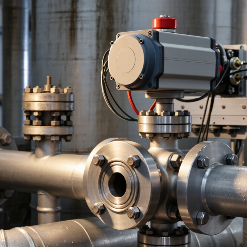
How to Choose an Automated Ball Valve?

What an Automated Ball Valve Is and How It Works

How to Choose an Automated Ball Valve?

What an Automated Ball Valve Is and How It Works

An automated ball valve combines a quarter-turn valve with an electric or pneumatic actuator. Inside the valve body, a drilled ball rotates to control fluid flow. When the opening aligns with the pipeline, fluid passes through. A 90-degree turn closes the passage tightly.

The actuator receives a control signal from a switch, controller, or process system. It then turns the valve stem to the required position. Electric models use a motor and gears, while pneumatic models use compressed air. Some actuators include position feedback, manual overrides, and fail-safe functions. These details matter during power loss or emergency shutdowns.

Choosing one requires more than matching pipe size. Check the fluid, pressure, temperature, flow rate, and connection standard. The actuator must provide enough torque, including extra force for sticky or contaminated media. In field inspections, I have seen undersized actuators stall before full closure. That mistake can cause leakage and process interruptions.

A suitable enclosure rating protects the actuator from dust and moisture. For outdoor service, weather exposure deserves careful attention. Control voltage and signal type must also match the existing system. The first selection is rarely perfect. Recheck the valve cycle time, maintenance access, and installation position before ordering. A manual override can be useful, but it may create confusion if operators lack clear instructions.

How to Choose an Automated Ball Valve?

What an Automated Ball Valve Is and How It Works

An automated ball valve combines a quarter-turn ball valve with an electric, pneumatic, or hydraulic actuator. The actuator rotates the valve stem by approximately 90 degrees to move the ball between the open and closed positions. The chart shows representative full-stroke times: pneumatic actuators are commonly the fastest, while electric actuators are often selected when precise positioning, simple wiring, and lower utility requirements are important. Actual performance depends on valve size, torque, pressure, actuator sizing, and control configuration.

Key Valve Specifications to Define Before Selection

Choosing an automated ball valve starts with defining the service conditions, not the actuator. Record the fluid, pressure, temperature, flow rate, and pipe size. Water, steam, oil, and corrosive chemicals demand different body and seal materials. A clean-looking specification sheet can still hide a poor match.

Check the valve’s pressure rating at the actual operating temperature. Confirm whether the port is full bore or reduced bore, because this affects pressure loss. Measure required torque with a safety margin, especially for sticky or infrequently operated media. Electric actuators suit controlled, repeatable movement, while pneumatic units can provide faster cycling. Consider the available power and the expected number of cycles. Keep it practical.

Control details matter in real installations. Define the signal type, feedback method, enclosure protection, and manual override requirements. For hazardous or outdoor areas, verify the applicable safety and environmental standards. A spring-return actuator may protect the process during power loss, but its fail position must match the equipment’s risk assessment. Incorrect assumptions here can create serious downtime.

Installation space is easy to underestimate. Leave room for wiring, maintenance, and actuator removal. I have seen compact valves selected correctly on paper but blocked by nearby pipe supports. That mistake is avoidable. Review the complete assembly, not only the valve body. Document every assumption, including fluid cleanliness and shutoff expectations. Some choices remain uncertain until operating data is available. Testing one sample under real conditions may reveal more than another hour of browsing catalogs.

How to Choose an Automated Ball Valve? - Key Valve Specifications to Define Before Selection

Specification What to Define Before Selection Typical Values or Options Selection Guidance
Valve Size and Connection Nominal pipe size, connection standard, and installation dimensions. DN8 to DN300; threaded, socket-weld, butt-weld, flanged, or wafer connections. Match the valve port and end connection to the piping system. A full-port valve generally reduces pressure loss compared with a reduced-port design.
Valve Configuration Number of ports and flow-path arrangement. Two-way shutoff; three-way L-port or T-port; normally open, normally closed, or diverting service. Use a two-way valve for isolation. Select an L-port or T-port three-way valve according to the required mixing, diverting, or switching sequence.
Pressure Rating Maximum working pressure, pressure class, and differential pressure across the valve. PN10, PN16, PN25, PN40, Class 150, or Class 300, depending on design and standard. The allowable pressure depends on the body material, temperature, connection standard, and manufacturer rating. Include upstream pressure, downstream pressure, and shutoff differential pressure.
Operating Temperature Minimum and maximum process, ambient, and storage temperatures. Common industrial ranges may extend from approximately -40°C to 180°C; special designs can cover wider ranges. Check the temperature limits of the body, seats, stem seals, actuator enclosure, solenoid, and cable glands. The lowest-rated component determines the practical limit.
Medium or Fluid Compatibility Fluid type, concentration, cleanliness, viscosity, abrasiveness, and toxicity. Water, air, inert gas, oil, fuel, chemicals, steam, and other compatible liquids or gases. Confirm chemical compatibility for every wetted component. Slurries, abrasive fluids, crystallizing media, and contaminated fluids may require a different valve design.
Body Material Required corrosion resistance, strength, and temperature capability. Brass, bronze, carbon steel, stainless steel, or engineered plastic for suitable low-pressure applications. Use stainless steel or another corrosion-resistant alloy for many aggressive or hygienic services. Verify material compatibility rather than selecting by fluid name alone.
Ball and Stem Material Material exposed to the process and required wear or corrosion resistance. Stainless steel, plated alloy steel, or materials specified for the process conditions. The ball and stem should withstand the fluid, operating temperature, pressure cycling, and expected number of cycles without excessive wear or galling.
Seat Material Seat type, temperature range, chemical compatibility, and shutoff requirement. PTFE, reinforced PTFE, modified PTFE, PEEK, or elastomeric seats such as EPDM or FKM. Soft seats typically provide tight shutoff at moderate temperatures. High-temperature, abrasive, or severe-service applications may require a specialized seat material or metal-seated design.
Flow Coefficient and Pressure Drop Required flow rate, inlet pressure, outlet pressure, and allowable pressure loss. Specify liquid flow in m³/h or L/min, gas flow in Nm³/h or SCFM, and the required pressure drop. Use the manufacturer’s Cv or Kv data for sizing. Oversizing can reduce controllability and increase cost, while undersizing can restrict flow and raise pressure loss.
Actuator Type Available utilities, cycle frequency, torque requirement, and fail position. Electric, pneumatic double-acting, or pneumatic spring-return actuator. Electric actuators suit locations without instrument air. Pneumatic actuators are often preferred for rapid or high-cycle operation. Include a safety margin above the valve’s required breakaway and running torque.
Actuator Power or Air Supply Electrical voltage and frequency, or pneumatic pressure and air quality. Common electrical supplies include 24 VDC, 110 VAC, and 230 VAC; pneumatic supply is often approximately 4 to 8 bar. Confirm voltage tolerance, current draw, air pressure, air consumption, and available capacity. Use clean, dry instrument air when required by the actuator design.
Control Function Open/close operation, modulating control, switching speed, and positioning accuracy. On/off control; proportional control with 0–10 V, 4–20 mA, or digital communication. Standard ball valves are mainly used for isolation. For throttling, select a control-rated valve and actuator with suitable positioning feedback and a properly calculated flow characteristic.
Fail-Safe Position Required valve position after power, signal, or air failure. Fail-open, fail-closed, or fail-in-place. Choose a spring-return pneumatic actuator or an electric actuator with an appropriate emergency function when the process requires a defined safety position.
Cycle Time and Duty Cycle Required opening or closing time, cycles per hour, and continuous operating duration. From a few seconds for quarter-turn actuation to longer times for controlled electric operation; duty ratings vary by actuator. Verify actuator duty class, motor thermal limits, gearbox rating, and maximum cycles. High-frequency service may require an actuator specifically rated for frequent operation.
Leakage and Shutoff Class Permitted internal leakage and external stem or body leakage. Bubble-tight soft-seat shutoff may be available; metal-seated valves generally have specified allowable leakage. Define the required leakage standard in the purchase specification. Do not assume that every ball valve provides the same shutoff performance under all pressures and temperatures.
Environmental Protection Indoor or outdoor installation, moisture, dust, corrosion, vibration, and hazardous-area classification. Enclosure ratings such as IP65, IP66, or IP67; hazardous-area approval where applicable. Select the actuator and electrical accessories for the actual environment. Outdoor, washdown, marine, and hazardous locations may require enhanced enclosure or certification requirements.
Manual Override and Feedback Need for local operation, position indication, limit switches, and diagnostic signals. Manual override, visual indicator, open/closed limit switches, potentiometer, 4–20 mA feedback, or fieldbus communication. Add feedback when the control system must verify the actual valve position. Ensure the signal type and wiring match the PLC, DCS, or building automation system.
Standards and Certification Applicable design, testing, pressure equipment, electrical, hygiene, or hazardous-location requirements. Relevant ISO, IEC, ASME, EN, API, ATEX, IECEx, NSF, or other jurisdictional requirements, depending on service. Specify only certifications required by the application and local regulations. Confirm that the certification applies to the complete valve-and-actuator assembly where necessary.
Maintenance and Lifecycle Requirements Expected service life, spare parts, accessibility, cleaning method, and replacement time. Replaceable seats and seals, maintenance-free actuator gearing, or serviceable assemblies depending on design. Consider total cost of ownership, spare-part availability, inspection access, and compatibility with the site’s maintenance procedures before final selection.

Note: The listed values are typical specification ranges and should be verified against the final valve design, applicable standards, process calculations, and operating conditions.

Choosing the Right Actuator, Power Source, and Control Method

How to Choose an Automated Ball Valve?

Choosing the Right Actuator, Power Source, and Control Method

An automated ball valve should match the process, not just the pipe size. Start with the valve’s torque requirement under real operating conditions. Fluid pressure, temperature, seat material, and long idle periods can increase starting torque. A practical selection adds a measured safety margin. Too little margin causes failed movement. Too much can increase cost and wear.

Pneumatic actuators suit facilities with reliable compressed air and frequent cycling. They respond quickly, but air quality and pressure must remain stable. Electric actuators work well where air systems are unavailable. Check duty cycle, enclosure rating, emergency behavior, and power loss response. A 24-volt supply may be convenient for controls, while higher voltage can support larger actuators. Keep wiring distance in mind. Voltage drop is easy to overlook.

The control method should reflect the process risk. Simple open-close service may use limit switches and a basic relay signal. Modulating service requires accurate position feedback and suitable control logic. Confirm whether the system needs local control, remote commands, or both. In field commissioning, incorrect fail-position assumptions often create delays. I have also seen torque estimates based only on clean water. That can be optimistic when the line carries solids or becomes idle for months. Test the assembled valve when possible, and document the selected actuator, power source, signals, and failure position. Allow margin.

Matching Valve Materials to Fluid, Pressure, and Temperature

How to Choose an Automated Ball Valve?

Choosing an automated ball valve starts with the fluid, not the actuator. Identify every wetted material, including the body, ball, stem, seats, and seals. Water, oils, acids, solvents, and abrasive slurries create different risks. Stainless steel may resist corrosion well, but it is not automatically suitable. Some chemicals attack it under heat or pressure.

Check the valve’s pressure-temperature rating at the actual operating conditions. Do not rely only on the catalog’s maximum pressure. Higher temperatures can reduce material strength and change seat performance. PTFE seats often handle many chemicals, while reinforced polymers may suit higher pressure. Elastomer seals require careful temperature and fluid compatibility checks. Small mismatches can cause swelling, leakage, or early failure.

Pressure drops matter too. A partly closed ball valve can generate heat, noise, or cavitation in liquid service. For abrasive media, hardened trim may extend service life, though it cannot prevent every failure. Select the actuator after confirming required torque, operating speed, and fail position. I have seen projects specify the actuator first, then discover that the seat material was unsuitable. That is an expensive lesson.

Leave room for doubt. Fluid composition can change, especially in process lines. Review the safety data, pressure range, temperature cycles, and cleaning chemicals with a qualified engineer. Test uncertain combinations before full installation. Real operating conditions often differ from the original design sheet.

Installation, Maintenance, Safety, and Performance Checks

How to Choose an Automated Ball Valve?

Installation, Maintenance, Safety, and Performance Checks

Choose an automated ball valve by matching media, pressure, temperature, pipe size, and operating frequency. The actuator must deliver enough torque during start-up, not only during normal running. Confirm the mounting interface, stem dimensions, and flow direction before installation. A small alignment error can create leakage and excessive wear. ISO 5211 provides useful guidance for actuator-to-valve mounting, while ISO 5208 defines industrial valve leakage testing.

Safety requires more than a fail-closed label. Check the actual spring-return position, emergency power behavior, manual override, and electrical enclosure rating. A pneumatic actuator also needs clean, regulated air. The U.S. Department of Energy reports that compressed-air leaks can waste 20% to 30% of compressor output. That loss can weaken actuator response and increase operating costs. Incomplete risk reviews remain common. A valve can pass a bench test and still fail under heat, vibration, or dirty media.

Tips: Record baseline opening and closing times. Inspect stem seals, fasteners, wiring, and air tubing during scheduled maintenance. Repeat cycle and leak tests after repairs. Compare measured torque with the manufacturer’s certified data. Do not trust appearance alone. A clean valve may still be misaligned. Leave room for better documentation; many maintenance records are too vague to support reliable decisions. Use recognized standards, calibrated instruments, and competent technicians for final verification.

FAQS

What information should be defined before selecting an automated ball valve?

Record the fluid, pressure, temperature, flow rate, pipe size, and expected cycling frequency. Water and corrosive liquids need different materials.

Why must pressure ratings be checked at operating temperature?

A valve rating can change as temperature rises. Confirm the rating under actual conditions, not only at room temperature.

What is the difference between full-bore and reduced-bore valves?

A full-bore passage usually creates less pressure loss. A reduced-bore design may affect flow, especially in high-demand lines.

How should the actuator torque be selected?

Measure torque under real conditions and add a practical safety margin. Sticky media and long idle periods can increase starting torque.

When is a pneumatic actuator suitable?

Pneumatic actuators fit facilities with stable compressed air and frequent cycling. They respond quickly. Air quality still matters.

When should an electric actuator be considered?

Electric actuators suit installations without reliable compressed air. Check duty cycle, power loss behavior, enclosure protection, and wiring distance.

What control details should be confirmed?

Define the signal type, feedback method, local controls, remote commands, and manual override. Simple open-close service may need only limit signals.

How can installation problems be avoided?

Review the complete valve assembly and leave space for wiring, maintenance, and removal. A nearby pipe support can block an actuator.

What does a fail position mean, and why is it important?

The fail position describes the valve’s response during power loss. Confirm that open or closed behavior matches the process risk assessment.

Should the selected valve be tested before full installation?

Testing one assembled sample under real conditions can reveal hidden torque or sealing issues. Catalog data is helpful, but sometimes optimistic.

Conclusion

Selecting the right Automated Ball Valve begins with understanding how it operates: a rotating ball controls fluid flow, while an actuator opens, closes, or regulates the valve according to a control signal. Before choosing a model, define the required valve size, connection type, pressure rating, flow rate, shutoff performance, and operating cycle. These specifications help ensure reliable performance and compatibility with the system.

The actuator should match the available power source, such as electric, pneumatic, or hydraulic energy, as well as the required control method and response speed. Valve materials must also be suitable for the fluid’s chemical properties, temperature, and pressure to prevent premature wear or leakage. Proper installation, routine maintenance, and safety checks are essential for long-term operation. After installation, verify flow direction, actuator movement, sealing performance, control signals, and emergency functions to confirm that the Automated Ball Valve performs safely and efficiently.

Sienna

Sienna

Sienna is a skilled marketing professional with a deep expertise in our company’s core products and services. With a passion for innovation and detail, she plays a pivotal role in crafting insightful blog posts that not only highlight the unique features of our offerings but also provide valuable......